5.3.1. Purpose #
Visualization of the relationship between two channels within a selected frequency band.
5.3.2. Controls #
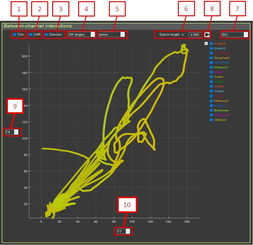
- Trim: Remove artifact segments
- CAR: Common average reference
- Denoise: Blink artifact suppression
- Filter: Frequency filter selection
- Amplitude/Power: Amplitude or power
- Epoch length: Epoch length
- Mode selection: Power by sections / Between-channel interactions
- Recalculation button
- Electrode Y: Channel for the Y-axis
- Electrode X: Channel for the X-axis
5.3.3. Calculation Method #
- Transformations and filtering are applied to each channel.
- The signal is converted to amplitude or power.
- Epoch averaging is applied.
- For each section, a scatter plot is built:
plot(X_channel, Y_channel)
5.3.4. Interpretation #
- Linear relationship: high correlation between channels
- Clusters: different sections may form separate clusters
- Cloud shape: reflects the type of interaction (synchronous, asynchronous, delayed)